
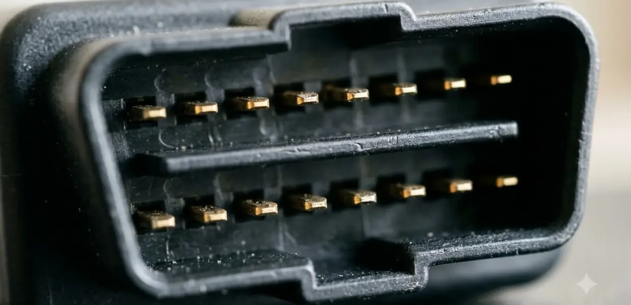

An OBD2 pinout is the fixed layout of the 16 pins in a car’s diagnostic port, defined by SAE J1962. Pin 16 carries battery power, pins 4 and 5 are grounds, and pins 6 and 14 carry CAN signals.
The 16 pins fall into three groups: power and ground, the data pins for each bus protocol, and manufacturer-specific pins that change by make. Check the OBD2 pinout for your protocol and make before you wire anything to a pin.
Electrical work on a vehicle can damage its modules or cause injury. Confirm pin roles in the service manual for your exact make, model and year before connecting a meter, adapter or cable.
What the OBD2 Pinout Covers
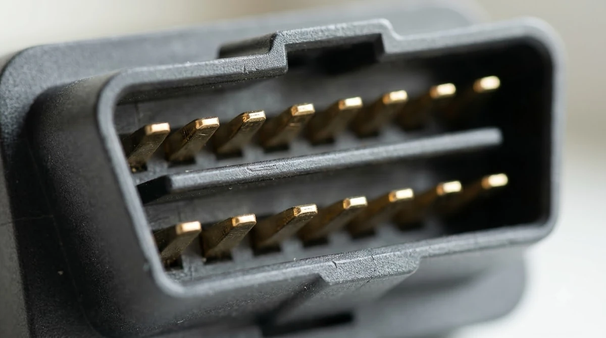
The OBD2 pinout is the set of 16 contacts defined by SAE J1962, the standard diagnostic link connector for OBD-II vehicles. SAE J1962 defines two connector types, Type A and Type B.
According to the OBD-II connector reference at OBDtester, the two types differ mainly in the shape of the alignment tab. The type matters for power, which the power section covers below.
Placement is also set by the standard. For Type A connectors, SAE J1962 says the port shall be in the passenger or driver compartment, in the area from the driver’s end of the instrument panel to 300 mm beyond the vehicle centerline.
The OBD2 pinout tells you what each contact is for. It does not tell you which codes a car has stored or which scanner to buy, and the OBD2 code readers for basic scans cover that side. You need the pinout mainly when you build a cable, test a port that seems dead, or read a bus signal directly.
OBD2 Pinout Table: All 16 Pins
The OBD2 pinout table lists the standard signal for each pin as shown by OBD Advisor and OBDtester, which agree on the core pins. Pins that the standard leaves to the manufacturer are marked as such, because their use changes by make and model. Check the table against your vehicle’s documentation before you rely on it.
| Pin | Standard signal | Notes |
|---|---|---|
| 1 | Manufacturer discretionary | Use varies by make |
| 2 | SAE J1850 bus positive | VPW or PWM |
| 3 | Manufacturer discretionary | Use varies by make |
| 4 | Chassis ground | Vehicle ground reference |
| 5 | Signal ground | Reference for data signals |
| 6 | CAN high | ISO 15765-4 and SAE J2284 |
| 7 | K-line (ISO 9141-2 and ISO 14230-4) | Serial data line |
| 8 | Manufacturer discretionary | Use varies by make |
| 9 | Manufacturer discretionary | Use varies by make |
| 10 | SAE J1850 bus negative | PWM only |
| 11 | Manufacturer discretionary | Use varies by make |
| 12 | Manufacturer discretionary | Use varies by make |
| 13 | Manufacturer discretionary | Use varies by make |
| 14 | CAN low | ISO 15765-4 and SAE J2284 |
| 15 | L-line (ISO 9141-2 and ISO 14230-4) | Optional |
| 16 | Battery power | 12 V on Type A, 24 V on Type B |
Pins 4 and 5 are listed separately as chassis ground and signal ground, so a cable that needs both references should carry both. Seven pins are left to the manufacturer, which is why a blank or unfamiliar pin does not automatically mean a fault.
Power and Ground Pins: 4, 5 and 16
Pin 16 carries battery power, supplying 12 volts at 4 amps on Type A and 24 volts at 2 amps on Type B, while pins 4 and 5 are the grounds. OBD Advisor’s pinout guide lists these supply figures for each connector type.
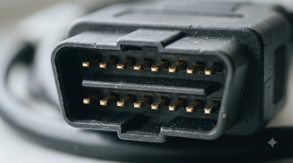
Treat those OBD2 pinout figures, as OBD Advisor reports them, as limits for any device that draws power from the port. Type B is the 24-volt version, so check the connector type before you assume a 12-volt supply. The two types differ in the alignment tab, so the port shape is the first clue.
Not every source gives the voltage. OBDtester lists pin 16 only as vehicle battery positive, so do not rely on one page alone. Measure the pin with a digital multimeter on your car and compare the reading with the service manual for your exact vehicle.
Grounds deserve the same care. Pin 4 is chassis ground and pin 5 is signal ground. If a tool powers on but cannot talk to the car, check the ground path before you suspect the protocol.
Communication Pins and Protocols
Three bus protocols use the OBD2 pinout: CAN on pins 6 and 14, SAE J1850 on pins 2 and 10, and the K-line on pin 7 with optional pin 15. Each one has its own pair or single line, so the pins a vehicle uses reveal its protocol. When CAN communication drops out, scanners report network codes such as those in the U0100 lost communication code guide.
CAN uses pin 6 for CAN high and pin 14 for CAN low, under ISO 15765-4 and SAE J2284. SAE J1850 uses pin 2 for bus positive and pin 10 for bus negative, and pin 10 is PWM only. The K-line runs on pin 7, with the L-line on pin 15 listed as optional.
| Protocol | Pins | Standard named |
|---|---|---|
| CAN | 6 (high), 14 (low) | ISO 15765-4 and SAE J2284 |
| SAE J1850 | 2 (positive), 10 (negative) | VPW or PWM; pin 10 is PWM only |
| K-line | 7, with 15 optional | ISO 9141-2 and ISO 14230-4 |
Read the OBD2 pinout for the pins a vehicle actually uses before you choose a cable. A cable built for one protocol may not reach a car that runs another, so match the cable to the protocol listed in the vehicle documentation. Wireless adapters, such as the Bluetooth OBD2 scanner picks, plug into the same 16-pin port.
Not every vehicle on this connector is a passenger car. According to the OBD-II PIDs article on Wikipedia, some heavy trucks use the same SAE J1962 connector but 29-bit CAN identifiers instead of the 11-bit identifiers used on passenger cars.
Manufacturer-Specific Pins Change by Make
Pins 1, 3, 8, 9, 11, 12 and 13 are left to each manufacturer, so the same pin can carry a different signal from one brand to another. An OBD2 pinout chart from one brand should never be assumed to match another.
OBD Advisor notes that manufacturers use these pins to send specific information. Audi and Volkswagen assign pin 1 to an ignition signal, while Infiniti and Nissan assign pin 1 to a CHECK signal. Those examples show why a pin label from one brand does not transfer to another.
Do not treat pin 1 as a universal power or ignition pin. Look up the make-specific OBD2 pinout or the service manual for the exact model year before you connect anything to a manufacturer pin. Where to confirm make-specific pins:
- The exact year, make, model and engine of the vehicle
- The service manual or wiring diagram for that model
- A make-specific pinout table from a source that names where its data came from
- A voltage check on the pin with a meter, with the key in the position the procedure specifies
Checklist Before You Wire to the OBD2 Pinout
Confirm the protocol, the connector type and the pin roles for your exact vehicle before you connect a meter, adapter or custom cable. The steps below cover the checks that come before any wiring.
- Record the vehicle’s year, make, model and engine.
- Confirm whether the port is Type A or Type B by its shape.
- Find the OBD2 pinout for that exact vehicle in the service manual, not only in a generic chart.
- Identify the protocol pins the vehicle uses, such as pins 6 and 14 for CAN.
- Measure pin 16 with a meter before you connect any load.
- Keep pins 4 and 5 connected when a tool needs a full ground path.
- Leave manufacturer-specific pins unconnected unless the documentation names their function.
This checklist covers reading and wiring the port only. It does not cover module programming or ECU repair, which need their own procedures and tools.
Frequently Asked Questions
Do all 16 pins on an OBD2 port carry a signal?
No. Seven pins in the OBD2 pinout are left to the manufacturer, and pin 15 is optional. An unused or unfamiliar pin therefore does not by itself mean the port or the scanner has failed.
Where is the OBD2 port located?
For Type A connectors, SAE J1962 places the port in the passenger or driver compartment, between the driver’s end of the instrument panel and 300 mm beyond the vehicle centerline. Check the owner documentation for the exact spot on your car.
Is pin 16 always 12 volts?
No. Type A connectors supply 12 volts and Type B connectors supply 24 volts, according to OBD Advisor. Confirm the connector type and measure the pin before you draw power from it.
Do I need an OBD2 pinout to read trouble codes?
Usually not. A standard code reader plugs into the port and handles the protocol itself, so the OBD2 pinout matters mainly for custom cables, adapters and diagnosing a port that does not respond.
Is it safe to probe OBD2 pins while the engine runs?
Only when a service procedure tells you to. A probe that touches the wrong pin can short a signal to ground and damage a module, so keep probes on the pins your documentation names.
What should I check if a pin looks missing or bent?
Inspect the connector for bent or corroded contacts, then confirm the protocol and pin roles for your exact vehicle. Repairs to a damaged port should follow the service manual rather than a guess.
Use this OBD2 pinout as a reference, not as a wiring guide. If you only need to read codes, a standard tool is enough and no wiring is required. Keep the table for cable building or port troubleshooting, and confirm every pin for your vehicle first.